
VIPANI DESIGN DOCUMENT
REQUIREMENT ANALYSIS
ANALYSIS MODEL
DESIGN AND DESIGN PATTERNS
INTRODUCTION
VIPANI is a configurable electronic marketplace which can be configured for selling and buying products and services. The design document of VIPANI is described in this page. It consists of the usecase diagrams, analysis and design models.
Use-case diagrams graphically depict system behavior (use cases).These diagrams present a high level view of how the system is used as viewed from an outsider’s (actor’s) perspective. A use-case diagram may depict all or some of the use cases of a system.
A use-case diagram can contain:
- actors ("things" outside the system)
- use cases (system boundaries identifying what the system should do)
- interactions or relationships between actors and use cases in the system including the associations, dependencies, and generalizations.
The following usecase diagram presents different important usecases int the context of VIPANI project. Registering, Logging in as buyer or seller, creating an auction etc are some of the major usecases.
Three of the important usecases are described in this section, one each from buyer, seller and system administrator perspective.
1.
Create
Auction Usecase
a.
Main Flow
i.
The Seller is
provided with a page where he provides details about product he wants to sell.
ii.
He specifies a
product, category, quantity, endtime for the auction,
type of auction (Dutch Auction or First Price Sealed
Bid). (E1)
iii.
He saves the
details. (E2)
iv.
He selects the
winner determination algorithm and price determination algorithm.
v.
He starts the
auction.
i.
(E1) The seller
does not provide correct details or some details or blank, then raise an error,
and show the same page.
ii.
(E2) If the endtime is already expired, raise an error and show the
same page.
2.
Browse product catalogue
a.
Main Flow
i.
The Buyer is
provided with a page where the top level categories of products are displayed.
ii.
Clicking on any
one of them, the subcategories under that category is displayed.
iii.
If no further sub
categorization exists, then the list of products under that category is
displayed.
iv.
If the user
clicks on the product, product details like owner of the auction, present bid,
quantity, etc are displayed and an option is given to the user to bid for that
product. (E1)
i.
(E1) The Buyer
has already bid for the product. A message is displayed to the user that he has
already bid for the product
3.
Add product category to product catalogue
a.
Main Flow
i.
The system admin
is provided with a page where the top level categories of products are
displayed.
ii.
If the system
admin wishes to add a new top level category, he clicks on add category
button and adds a new category
iii.
The system admin
can browse to a specific level and then click on add category button and add
a new category at any level (E1)
i.
(E1) An already
existing category is again added, an error message is provided to the user.
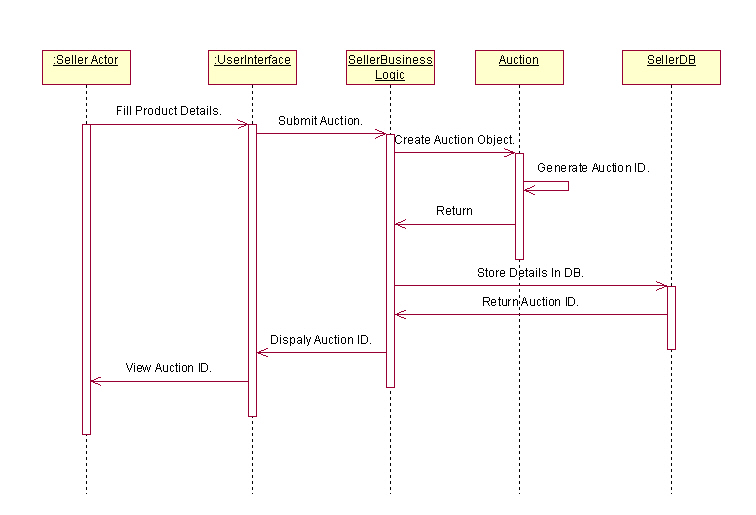
A sequence diagram is a graphical view of a scenario that shows object interaction in a time-based sequence - what happens first, what happens next. Sequence diagrams establish the roles of objects and help provide essential information to determine class responsibilities and interfaces.
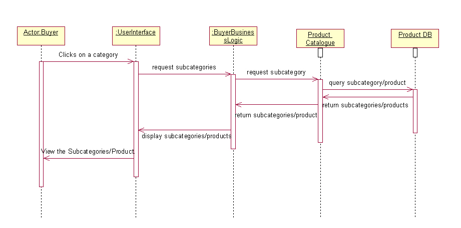
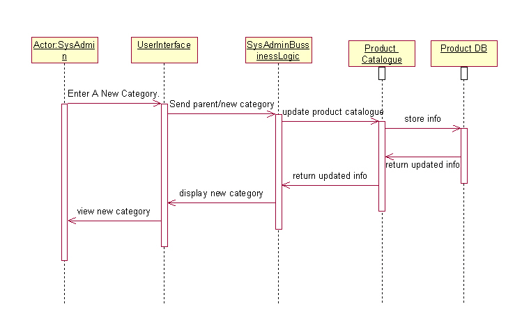
The three diagrams that follow show sequence diagrams for the three use case descriptions given in the previous section
a) Sequence Diagram for Creating an auction
b) Sequence Diagram for browsing the product catalogue
c) Sequence Diagram for add subcategory/product to product catalogue
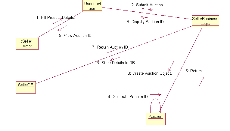
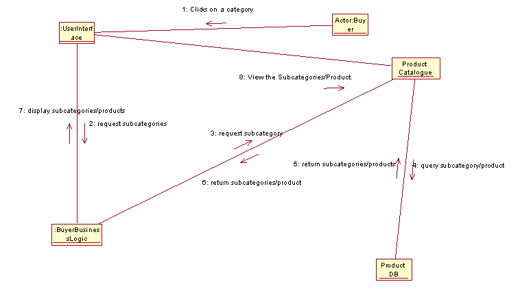
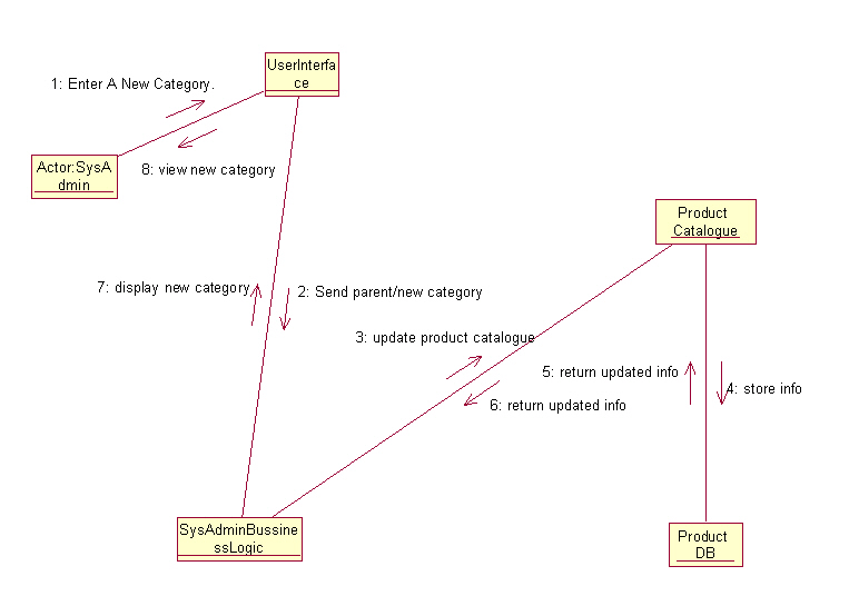
Collaboration diagrams and sequence diagrams are alternate representations of an interaction. A collaboration diagram is an interaction diagram that shows the order of messages that implement an operation or a transaction.
The following three diagrams represent the colloboration diagram for the three usecases described in the previous section.
a) Colloboration diagram for creating an auction
b) Colloboration diagram for browsing the product catalogue
c) Colloboration diagram for adding subcategory/product to product catalogue
A class diagram shows the existence of classes and their relationships in the logical design of a system. A class diagram may represent all or part of the class structure of a system.
The class diagram for VIPANI is shown below:
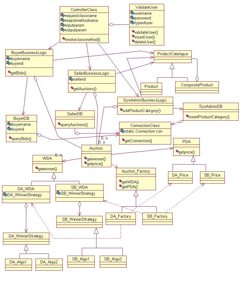 Several design patterns are used, which are described in the later sections
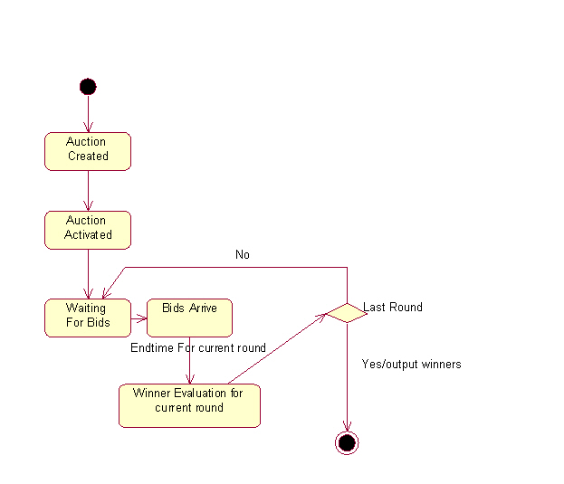
Statechart diagrams model the dynamic behavior of individual classes or any other kind of object. They show the sequences of states that an object goes through, the events that cause a transition from one state to another, and the actions that result from a state change.
A State Chart Diagram is shown below which describes the different states of an Auction object.
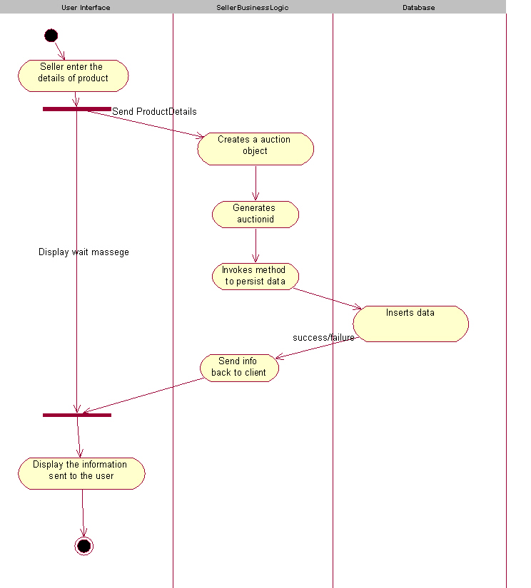
Activity diagrams provide a way to model the workflow of a business process. You can also use activity diagrams to model code-specific information such as a class operation. Activity diagrams are very similar to a flowchart because you can model a workflow from activity to activity.
The activity diagram below describes the business process of creating an auction by the seller.
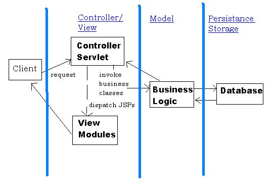
A 3-tier architecture will be used in implementing VIPANI. The model/view/controller pattern will be best suited for developing this application.
A variety of design patterns have been used in the design of VIPANI software. We illustrate four patterns in this section, giving details about how the patterns will be used in the VIPANI context.
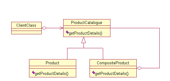
a) COMPOSITE PATTERN
Intent:- Compose objects into tree structures to represent part-whole hierarchies. Composite lets clients treat individual objects and compositions of objects uniformly.
In this case, the client can treat both simple product description and product category description uniformly.
b) ABSTRACT FACTORY PATTERN
Intent :- Provide an interface for creating families of related or dependent objects without specifying their concrete classes.
In this case, the Auction object can invoke the method 'getwinner' after obtaining the concrete class using the corresponding auction_factory object.
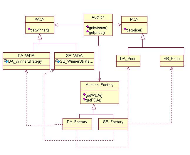
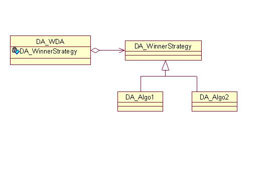
c) STRATEGY PATTERN
Intent: Define a family of encapsulated algorithms and make them interchangeable so each algorithm can vary independently from the clients that use it.
In this case, the winner algorithm is decided dynamically from a collection of algorithms as shown.
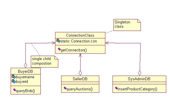
d) SINGLETON PATTERN
Intent: Ensure a class has only one instance and provide a global point of access
In this case, the Connection class is a singleton and the same connection is reused by all other objects.
e)MVC DESIGN PATTERN :
Intent: This design pattern provides mechanism to separate the Design model from the (user )interface of the application. The communication between the Design model and user interface is done with the control object.