TOPICS
:
1. SOFTWARE
INTENSIVE SYSTEM
Top
The architecture of the software-intensive system can best be described
by five interlocking views. Each view is a projection into the organization
and structure of the system, focused on a particular aspect of the system.

-
The use case view of a system encompasses the use cases that
describe the behavior of the system as seen by its end uses, analysts and
testers. This view doesn't really specify the organization of a software
system. Rather, it exists that shape the system's architecture. With the
UML, the static aspects of this view are captured in use case diagrams;
The dynamic aspects of this view are captured in interaction diagrams,
state charts and activity diagrams.
-
The design view of a system encompasses the classes, interfaces
and collaborations that form the vocabulary of the problem and its
solution. This view primarily supports the functional requirements, meaning
the services that the system should provide to its end users. With the
UML, the static aspects of the view are captured in the class diagrams
and object diagrams; the dynamic aspects of this view are captured in interaction
diagrams, statechart diagrams and activity diagrams.
-
The process view of a system encompasses the threads and processes
that form the system's concurrency and synchronization mechanisms. This
view primarily addresses the performance, scalability and throughput of
the system. With the UML, static and dynamic aspects of this view are capture
in the same kinds of diagrams as for the design view, but with a focus
on the active classes that represent these threads and processes.
-
The implementation view of a system encompasses the components and
files that are used to assemble and release the physical system.
This view primarily addresses the configuration management of the system's
releases, made up of somewhat independent components and files that can
be assembled in various ways to produce a running system. With the
UML, the static aspects of the view are captured in the component diagrams;
the dynamic aspects of this view are captured in interaction diagrams,
statechart diagrams and activity diagrams.
-
The deployment view of a system encompasses the nodes that form
the system's hardware topology on which the system executes. This view
primarily addresses the distribution, delivery and installation of the
parts that make up the physical system. With the UML, the static
aspects of the view are captured in the deployment diagrams; the
dynamic aspects of this view are captured in interaction diagrams, statechart
diagrams and activity diagrams.
Each of these
views can stand alone so that different stake holders can focus on the
issues of the system's architecture that must concern them. These five
views also interact with one another- nodes in the deployment view hold
components in the implementation view that, in turn, represent the physical
realization of classes, interfaces, collaborations, and active classes
from the design and process views. The UML permits you to express everyone
of these views and their interactions.
2. USE
CASES AND USE CASE DIAGRAMS Top
A use case diagram is a diagram that shows a set of use cases and actors
and their relationships.
2.1. CONTENTS
Use case diagrams commonly contain
-
Use cases
-
Actors
-
Dependency, Relationship, and association relationships.
2.2. USE CASES
-
A use case is a description of a set of sequence of actions, including
variants, that a system performs to yield an observable result of value
to an actor. Generally, a use case is rendered as an ellipse.
-
A use case describes a set of sequences, in which each sequence represents
the interaction of the things outside the system (its actors) with the
system itself (and its key abstractions).
-
A use case involves the interaction of actors and the system.
-
A use case describes what a system (or a subsystem, class, or interface)
does but it does not specify how it does it.
-
A use case represents a functional requirement of a system as a whole.
-
A use case may have variants.
2.3. ACTORS
-
An actor represents a coherent set of roles that users of use cases play
when interacting with these use cases.
-
Typically, an actor represents a role that a human, a hardware device,
or even another system plays with a system.
-
Actors are not actually part of the system. They live outside the system.
-
Actors may be connected to use cases only by association. An association
between an actor and a use case indicates that the actor and the use case
communicate with one another, each one possibly sending and receive messages.

The above figure is an example of a use case diagram which contains
actors, use cases and the relationship between these usecases.
2.4. COMMON USES OF USE CASES
The use case diagrams can be applied to model the static use case view
of a system. During modeling the static use case view of a system, use
case diagram can be used in one of two ways.
-
To model the context of a system
This involves drawing a line around the whole system and asserting
which actors lie outside the system and interact with it. The use case
diagrams can be applied to specify the actors and meaning of their roles.
-
To model the requirements of the system.
This involves specifying what the system should do (from a point of view
of outside the system), independent of how that system should do it. The
use case diagrams can be applied here to specify the desired behavior of
system.
In this manner, use case diagram lets you to view the whole system as
a black box; you can see what's outside the system and you can see how
that system reacts to the things outside, but you can't use how that system
works on the inside.
3. INTERFACES Top
An interface is a collection of operations that are used to specify
a service of a class or a component. Graphically, an interface is rendered
as a circle.
3.1. PROPERTIES OF INTERFACES
-
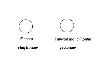
Every interface must have a name that distinguishes it from other interfaces.
A name is a textual string. That name alone is known as a simple name;
a
path name is the interface name prefixed by the name of the package
in which that interface lives. An interface may be drawn showing only its
name, as in the following figure:
-
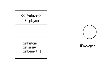
An interface is a named collection of operations used to specify a service
of a class or of a component. Unlike classes, interfaces do not specify
any structure (so they may not include any attributes), nor do they specify
any implementation (so they may not include any methods, which provide
the implementation of an operation). Like class, an interface may have
any number of operations. These operations may be adorned with all visibility
properties, tagged values, and constraints. When visualizing an interface
in the form of a circle, by definition, the display of these operations
is suppressed. The following figure depicts this.
-
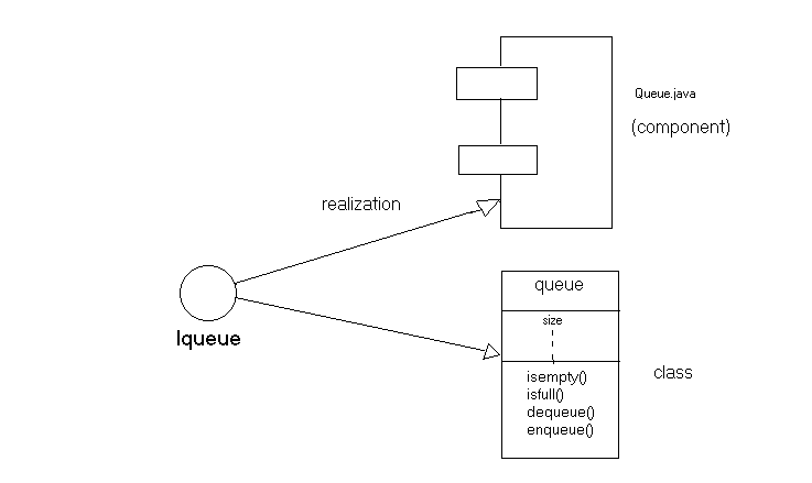
Like a class, an interface may participate in generalization, association,
and dependency relationships. In addition, an interface may participate
also in realization relationship. Realization is a semantic relationship
between two classifiers in which one specifies a contract that another
classifier guarantees to carry out. The following figure shows how an interface
participates in realization relationship.
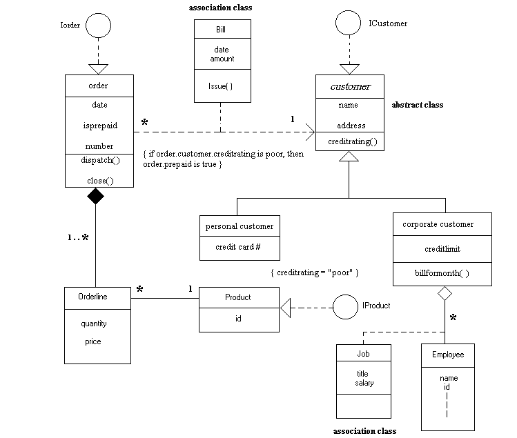
The following figure is an example which features abstract classes
, association classes, interfaces, classes and relationship among
these entities.
-
ABSTRACT CLASS : An abstract class is a class that cannot be instantiated.
In UML, an abstract class can be specified by writing its name in italics.
In the above figure, customer class is an abstract class.
-
ASSOCIATION CLASS : An association class is a modeling element that
has both association and class properties An association class can be seen
as an association that also has class properties, or as a class that also
has association properties. In UML, an association class can be represented
as a class attached by a dash line to an association. In the above figure,
Job and Bill are association classes.
4. COMPONENTS
Top
A component is a physical and replaceable part of a system that conforms
to and provides the realization of a set of interfaces. Graphically, a
component is rendered as a rectangle with tabs.
4.1. DEFINITION
Although most of the academic and industrial realm understands some
definition of a component, there tends to be some variance in what each
individual definition's of a component is. There are two key concepts essential
for understanding what is a component
-
A component is an implementation unit. It is the deployment of one or more
interfaces.
-
An interface is how a customer of a component views that component. For
the purpose of consuming a component, the consumer is concerned with the
interface they are consuming. Since the component is the implementation
of an interface, the consumer's
4.2. PROPERTIES OF COMPONENTS
-
Every component must have a name that distinguishes it from other component.
A name is a textual string. Similar to Interfaces, components too will
have simple name and path name. A component is typically drawn by showing
only its name. Just as with classes, components are adorned with tagged
values or with additional compartments to expose their details.
4.3. COMPONENTS AND CLASSES
4.3.1. Similarities:
-
Both have shape.
-
Both may realize a set of interfaces.
-
Both may participate in dependency, generalization, and association
relationships.
-
Both may have instances.
-
Both may be nested.
-
Both may be participants in interaction.
4.3.2. Differences:
-
Classes represent logical abstractions; components represent physical things
that live in the world of bits. In short, components may live on nodes,
classes may not.
-
Components represent the physical packaging of otherwise logical components
and are at a different level of abstraction.
-
Classes may have attributes and operations directly. In general, components
only have operations that are reachable only through their interfaces.
4.4. COMPONENTS AND INTERFACES
An interface is a collection of operations that are used to specify
a service of a class or a component. The relationship between component
and interface is important. All the most common component-based operating
system facilitates (such as COM+, CORBA and Enterprise Java Beans) use
interfaces as the glue that binds components together.
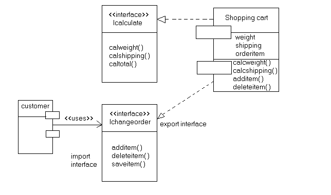
4.4.1. Export Interface:
An interface that a component realizes is called an export interface,
meaning
an interface that the component provides as a service to other components.
A component may provide many export interfaces.
4.4.2. Import Interface:
The interface that a component uses is called an import interface,
meaning
an interface that the component conforms to and so builds on. A component
may conform to many import interfaces.
A component may both import and export interfaces.
The following figure depicts both import and export interfaces
4.5. KINDS OF COMPONENTS
There are three kinds of components. They are:
-
Deployment components : These are the components necessary and sufficient
to form an executable system, such as dynamic libraries (DLLs) and executables
(EXEs). The UML's definition of component is broad enough to address classic
object models, such as COM +, CORBA, and Enterprise Java Beans, as well
as alternative object models, perhaps involving dynamic Web pages, database
tables, and executables using proprietary communication mechanisms.
-
Work product components : These components are essentially the residue
of the development process, consisting of things such as source code files
and data files from which deployment components are executed. These components
do not directly participate in an executable system but are the work products
of development that are used to create he executable system.
-
Execution components : These components are created as a consequence
of an executing program, such as COM+ object, which is instantiated from
a DLL.
4.6. STEREOTYPES AND COMPONENTS
4.6.1. DEFINITION OF STEREOTYPE
A stereotype extends the vocabulary of the UML, allows to create
new kinds of building blocks that are derived from existing ones
but that are specific to the problem.
The stereotypes are used generally to specify new kinds of components.
The UML defines five standard stereotypes that apply to components:
executable: specifies a component that
may be executed
library : specifies a static
or dynamic object library
table : specifies
a component that represents a database table
file : specifies
a component that represents a document containing source code or data
document : specifies a component that
represents a document
4.6.2. USES OF COMPONENTS
Components can be mainly used in one of the
following purposes:
-
To model the executables and libraries
-
To model the tables, files and documents
-
To model an API
-
To model source code
5.
COMPONENT DIAGRAMS
Top
5.1. CONTENTS
Component diagrams mainly contain
-
Components
-
Interfaces
-
Dependency, generalization, association and realization diagrams
Like all diagrams, component diagrams may contain notes and constraints.
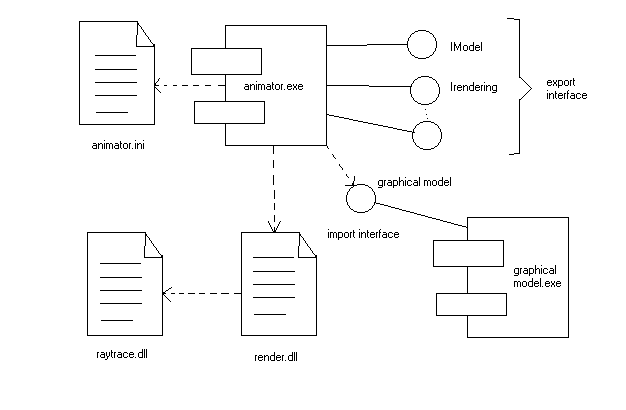
The following figure is an example of a component diagram which contains
components, interfaces and relationships.
5.2. USES OF COMPONENT DIAGRAMS
The component diagrams are mainly used to model the static implementation
view of a system. This view primarily supports the configuration management
of a system's parts, made up of components that can be assembled in various
ways to produce a running system.
While modeling the static implementation of a system, component diagrams
are typically used in one of the following ways.
With most contemporary object-oriented programming languages , code is
cut using integrated development environments that store the source code
in files. We can use component diagrams to model the configuration management
of these files, which represent work-product components.
-
To model executable releases
A release is a relatively complete and consistent set of artifacts delivered
to an internal or external user. In the context of components, a release
focuses on the parts necessary to deliver a running system. When you model
a release using component diagrams, you are visualizing, specifying and
documenting the decisions about the physical parts that constitute your
software.-that is its deployment diagrams.
-
To model physical databases
The model of a physical database represents the storage of that information
in the tables of a relational database or the pages of an object-oriented
database. Component diagrams are used to represent these kinds of physical
databases.
-
To model adaptable system
The components in a static system enter the scene, participate in an execution,
and then depart whereas the components or mobile agents in a dynamic system
migrate for purposes of load balancing and failure recovery. The component
diagrams are used in conjunction with some of the UML diagrams for modeling
behavior to represent these kinds of systems.
6.
UML DIAGRAMS HIERARCHY
Top
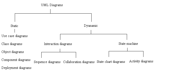
The following figure describes the hierarchy of UML diagrams :
7. ADDITIONAL
INFORMATION REGARDING SOFTWARE COMPONENTS AND COMPONENT-BASED SYSTEMS
Top
7.1.DEFINITIONS OF SOFTWARE COMPONENTS
-
A software component is a physical packaging of executable software
with a well-defined and published interface.
-
According to D'Souza and Wills, "A software component is a coherent
package of software artifacts that can be independently developed and delivered
as a unit and that can be composed, unchanged, with other components to
build something larger".
-
According to Szyperski, " A software component is a unit of
composition with contractually specified interfaces and explicit context
dependencies only. A software component can be deployed independently and
is subject to composition by third parties"
-
The current UML specification, UML 1.3 defines component as "A physical,
replaceable part of a system that packages implementation and provides
the realization of a set of interfaces." A component represents a physical
piece of implementation of a system, including software code (source, binary
or executable) or equivalents such as scripts or command files.
Software developers have long held the belief that complex systems can
be built from smaller components, bound together by software that creates
the unique behavior and forms of the system. Ideally, a new system can
be built using mostly pre-defined parts, with only a small number of new
components required. However, there are two engineering drivers in the
development of a component-based system:
-
Reuse : The ability to reuse existing components to create a more
complex system.
-
Evolution : By creating a system that is highly componentized, the
system is easier t maintain. In a well-designed, the changes will be localized,
and the changes an be made to the system with little or no effect on the
remaining components.
The notion of a component is a refinement of the concepts that have been
a part of adopting object-oriented techniques. A component is a
physical manifestation of an object that has a well-defined interface and
a set of implementations for the interface. The component itself may or
may not have been created using OO tools and languages.
7.2. OBJECT MODELS AND COMPONENT MODELS
In order for component-based system to work, it is necessary to
have a component model on which to base the deployment and communication
of the components. Two components can communicate only if they share a
mechanism for finding each other and sending messages. In most operating
systems, the common mechanism is some version of a common calling sequence
for procedures, allowing procedures written in different languages to call
each other. Like the object models, components need to have a reference
mode they can assume for purposes of interface definitions, message passing,
and data transfer. Some of the current component models are DCOM
(Distributed Component Object Model), CORBA (Common Object Request Broker
Architecture), EJB (Enterprise Java Beans). But in all these three models
, there is an issue of platform dependencies. An alternative is to connect
components through XML (Extensible Markup Language). Here, a component
implements a single interface that accepts XML messages. This solution
is suitable primarily for low-frequency, high semantic content exchanges,
such as passing purchase order information, patient records, or complex
requests.
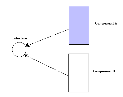
The most important distinguishing factors in component-based development
is the separation of the interface and the implementation. The interface
itself can be registered and subsequently identified in searches. The interface
is realized, or implemented, by one or more components, as shown in the
figure below
7.3. COMPONENT GRANULARITY
Component design decisions are driven by a variety of factors- foremost
are several design constraints that help define the range of component
granularity. Typically, intercomponent communication is fairly expensive
in terms of time and platform resources. Thus, the components are encouraged
to be larger rather than smaller. However, the larger the component , the
less flexible is the structure of the system. The principles of cohesion
and coupling are the factors. Minimizing the coupling of the system tends
to work against good cohesion.
7.4. COMPARISON OF SUBSYSTEM,CLASS AND COMPONENTS
Subsystem : A grouping of model elements that represent a behavioral
unit in a physical system. A subsystem offers interfaces and has operations.
In addition, the model elements of a subsystem can be partitioned into
specification and realization elements.
Class : A description of a set of objects that share the same
attributes, operations, methods, relationships and semantics. A class may
use a set of interfaces to specify collections of operations it provides
to its environment.
The three classifiers, components, classes and subsystems can have operations
and interfaces, may be associated with other classifiers, can be nested,
and may create instances. Components are similar to subsystems and differ
from classes in that they cannot have threads of control and they represent
units in physical systems. Components differ from subsystems and classes
because they are not a grouping construct; they alone can contain the implementation
of model elements, and their instances typically reside on computational
nodes. Only subsystems can import or access other model elements.
It is important to note that, while all three classifiers may conform to
a set of interfaces, interfaces are usually most closely associated with
components. Although it is relatively common to see a class without an
interface during analysis, and subsystems may use model elements other
than interfaces for specification ( for example, use cases and statecharts),
a component without an interface may be technically well-formed but suspect.
This is reflects the long-standing and intimate relationship between component-based
development and interface-based design.
In general, components and subsystems tend to be more coarse-grained than
classes. Indeed, it is common for a component to implement multiple design
classes. Similarly, it is typical for a subsystem to model the specification
and realization of a set of model elements, which may include both specification
types and implementation classes. Components are further distinguished
from the subsystems and classes in that they are typically modeled during
the implementation phase (compare analysis and design phases). It is important
to note however, that the classes and/or subsystems specifying components
and frameworks may be modeled during an earlier during an earlier life-cycle
phase, such as analysis or design.
7.5. MODELING COMPONENT FRAMEWORKS
Components are quite essential software building blocks that can be
recursively composed to build systems of increasing size and complexity.
Just as the hardware industry has used integrated circuits to recursively
build larger and more complex hardware components, the software industry
now endeavors to do something similar with software components. Component
frameworks are important mechanisms being used to accomplish this.
A framework is a generic term for
a powerful object-oriented reuse technique that typically emphasizes the
reuse of design patterns and architectures.
7.6. DEFINITION OF FRAMEWORK
-
A framework is a reusable design of all or a part of system represented
by a set of abstract classes and the way their instances interact.
-
A framework is the skeleton of an application that an be customized by
an application developer.
-
According to UML, framework is a stereotyped package consisting mostly
of patterns, an architectural pattern that provides an extensible template
for applications within a specific domain.
EJB and COM+ are examples of component frameworks that are industry standards
for building enterprise applications
8. LESSONS LEARNED
THROUGH SIX YEARS OF COMPONENT-BASED DEVELOPMENT
Top
8.1. COMPONENT DEFINITION
"A component is a language neutral, independently implemented
package of software services, delivered in an encapsulated and replaceable
container, accessed via one or more published interfaces". While a component
may have ability to modify a database, it should not be expected to maintain
state information. A component is not platform-constrained nor is it application
bound.
The statement that " A given component specification
may be realized in one or more implementation technologies." is reasonably
simple to make given our historical development tool, but it has become
increasingly difficult to adhere to as we have adopted newer implementation
tools and approaches.
Solutions were built with 4GL-based case
tools. our primary development tool has had minimal to nonexistent support
for components. through the use of naming standards, alternative process
approaches, a large mount of ingenuity, and an organizational desire to
succeed with components, we have been successful in practicing component-based
development (CBD). The past year has seen us transitioning from our traditional
4GL tools to Enterprise Java Beans (EJBs) and COM+.
8.2. CHALLENGES ASSOCIATED WITH ADOPTION OF CBD
Throughout the change in technologies, the lessons learned in the creation
and management of component-based system. These lessons apply to component-based
development in general, whether using development tools and programming
languages that treat components and interfaces as first-class elements
or not
-
Lesson 1 is the importance of a component reference
model, which serves as a guide through analysis and development.
-
Lesson 2 concerns things to watch for in
parallel development .
-
Lesson 3 examines the pros and cons of reuse .
-
Lesson 4 discusses immutability as it relates
to components .
-
Lesson 5 looks how prototypes are an important
part of selling CBD to an organization and succeeding with CBD projects
.
-
Lesson 6 describes experience with error and exception
handling and how they may be different in a networked solution.
-
Lesson 7 looks at changes to testing strategies
brought about by CBD.
Lesson 1 : Base your development on a component
reference model.
Requirements and scope changes in an information technology project,
when managed correctly, are positive if they result in a solution that
better satisfies the customer's needs. Change in the deployment targets
or the technical standards once the project is under way should be avoided.
The component reference model is composed of :
-
Descriptions of the goals of CBD
-
A set of design principles and modeling standards
-
A standard set of analysis, design, development and testing tools
-
A uniform set of documentation standards
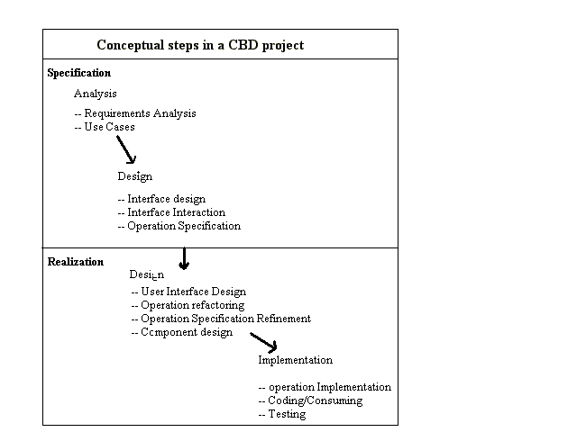
The component reference model has been our most valuable resource
across each of our successful projects.
Lesson 2 : Parallel development.
One of the goals we felt CBD would help us achieve was the ability to
split our project teams into multiple groups to work in parallel on a given
project. differences between a traditional project life cycle and a component-based
approach are shown in the table below, showing how parallel development
may be used
|
Basic project Process |
Component-based
approach |
| Understand the requirements |
Understand the requirements |
| Complete analysis and design |
Specify the components and their interactions |
| Code |
Parallel design |
| Test |
Parallel coding |
| Fix bugs |
Test each component in isolation |
| Retest |
Integrate components with application workflow |
| Deploy |
Application testing , Deployment |
A parallel development stream means that many jobs, such as developing
code, user interfaces, or collaborations, are based on specifications prepared
by a team separate from the developers.
Lesson 3 : Pros and cons of reuse.
While reuse of software assets is only one of the goals of a component-based
approach, it is often a key selling point . The idea that an organization
could utilize existing software when creating a new solution is understandably
appealing. Another popular reuse fallacy is that every component should
be engineered to be reusable, regardless of whether or not an organization
can identify what the future requirements of component will be.
Lesson 4 : Immutability and components.
Immutability is one of the most contentious topics encountered so far.
The issue can e stated as : " When is a component or interface considered
published and, thus, must be considered immutable and when can we allow
it to be change without versioning the component or interface ?"
If a change is made to the component operation, modifying its
behavior, it is difficult to argue against versioning the interface.
Versioning would prevent a consumer of previous interface from receiving
an interface different to their expectations. An approach called " modify
and notify" solves this problem a little.
Current implementation technologies such as COM +, EJB have done a little
to address the danger of misinterpretation of the specification.
Lesson 5 : Prototype early and often.
When you open Visual Basic , drag components from the tool palette onto
a form, and construct a basic interface. This example is a demonstration
of CBD and prototyping. Each of those visual controls is a language-independent
package of software services : a component.
Prototyping, helps to build active prototypes from a collection of components
which is useful to ease the adoption of a component-based approach.
Prototypes have many advantages :
-
Establishing the application's goals and component boundaries before we
have committed a large numbers of developers
-
Acting as a powerful demonstration tools, especially when selling CBD to
a new organization.
-
They show how distributed components help solve some traditional application
problems such as load balancing, data distribution, and replication.
-
They often point out potential problems in the component collaborations.
Lesson 6 : Err on the side of too much information.
All components eventually have to communicate something other than successful
result back to a consumer. When considering an approach to error handling
for component-based systems, it was found that it is important to consider
more than just the needs of just single application.
Lesson 7 : Testing strategies change.
When developing a component-based solution, traditional testing strategies
are altered to support the changes that CBD makes to the project
life cycle. Testing of a component-based solution is best viewed as two
distinct activities : the testing of the components, and the testing of
the assembled solution.
Because a component is an independently implemented module of software,
this suggests it can be tested as a standalone unit . But , now-a-days
both discrete component-level-testing, based on test plans prepared by
the component architects, and regressive application testing, based on
scenarios prepared by the application architects.
9.REFERENCES
Top
-
The Unified Modeling Language User's Guide - Grady Booch, James
Rumbaugh and Ivar Jacobson.
-
COMMUNICATIONS OF ACM OCTOBER 2000/Vol.43.No.10.
-
www.celigent.com/omg/umlrtf
is the OMG UML Revision Task Force home page. Contains UML specification
artifacts, including the latest UML specification and drafts of works-in-progress.
Also includes a link to the UML 2.0 Working Group page.
-
www.java.sun.com/products/ejb/
is the Enterprise Java Beans home page. Contains links to diverse resources
related to EJB, including specifications, white papers, and tutorials.
-
java.sun.com/aboutJava/communityprocess/
is the Java community process home page. Contains information about JCP
process, specification proposals, calls for experts and specification drafts.
-
www.microsoft.com/com/tech/complus.asp
is the COM+ page. Contains links to a wide range of resources related
to COM+, including white papers, presentations,and books.
-
www.sei.cmu.edu/cbs/cbse2000/papers/03/03.html
.Exploring a Comprehensive CBD method
-
www.cse.ucsc.edu/research/surf/users-manual/node94.html
Component definitions by Darnauer J.


